The images below demonstrate the efficiency of designing in CAD.
This is an overall view of a dining room proposal. Editing details in the room can be difficult when walls block access to details beyond a wall.
With one click, any wall can be hidden, enabling the technician unobstructed access to any of the objects in the room. This makes the design process very efficient, and making it cost effective for the customer.


CAD enables visual presentations of a project in a manner that is more intuitive for the viewer.


These images show how this model of a gate can be displayed in perspective, with dimensions, in a manner that is much easier to understand than multiple standard plan and elevation views. This can be especially helpful for non-professionals to understand how something is to be assembled.

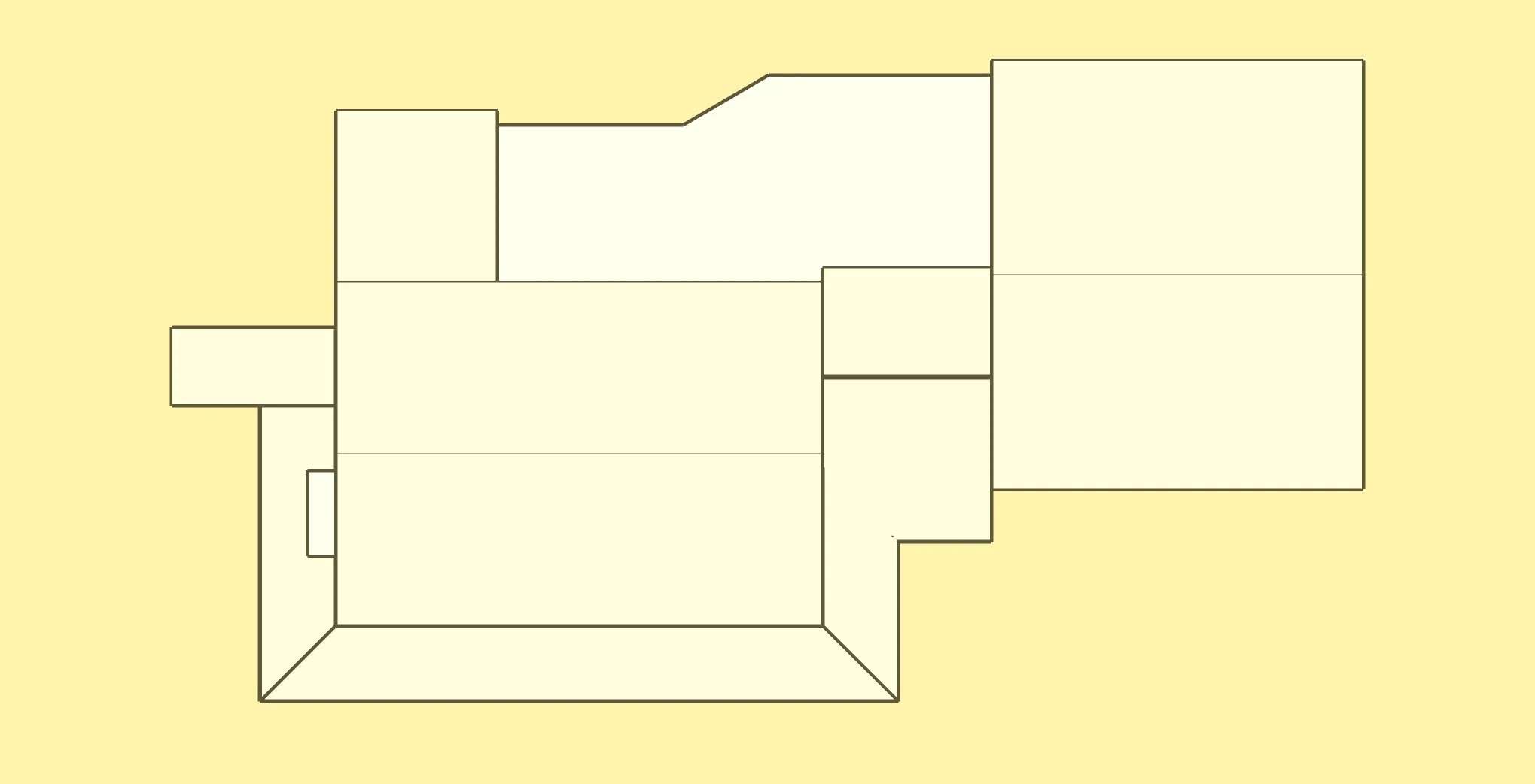
This is a simple design of a drying rack, made out of 2X4s and 1 inch dowels.


If a customer has a survey of a proposed, or existing building site, we can produce a model from the survey headings. Placing a new building on the site that is within building code setbacks is critical, and extremely important with smaller plots. Code officers will require accurate drawings before issuing a building permit.


The image below is a tent frame designed to replace a 10’ by 10’ metal frame that had been destroyed by high winds. The canopy was not damaged, so what was needed was a frame that could withstand adverse weather. We were asked to design a simple tent frame out of 2X4 lumber.
The frame design does not conform to any building standards. Being able to visualize the frame from any angle makes the sequence of assembly easy to understand. Having precise dimensions, including rafter pitch, would be essential to produce this frame. The design had to take into consideration the possibility of a permanent roof being added in the future. This is where CAD is really important. The edges of the rafters on each side must be on exactly the same plane for the installation of sheathing. There is a lot of complicated math involved in this design, and all of it is done with precision by the software.

This video will illustrate how unusual the construction is, and helps a builder understand the sequence of assembly.
Going from imagination to drawings a builder can work with.
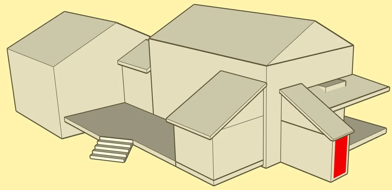
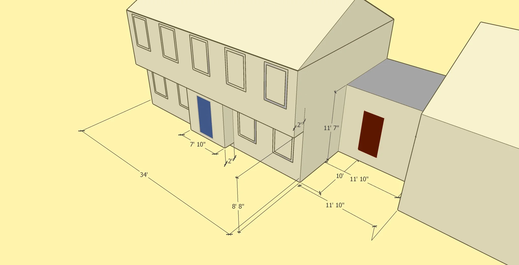
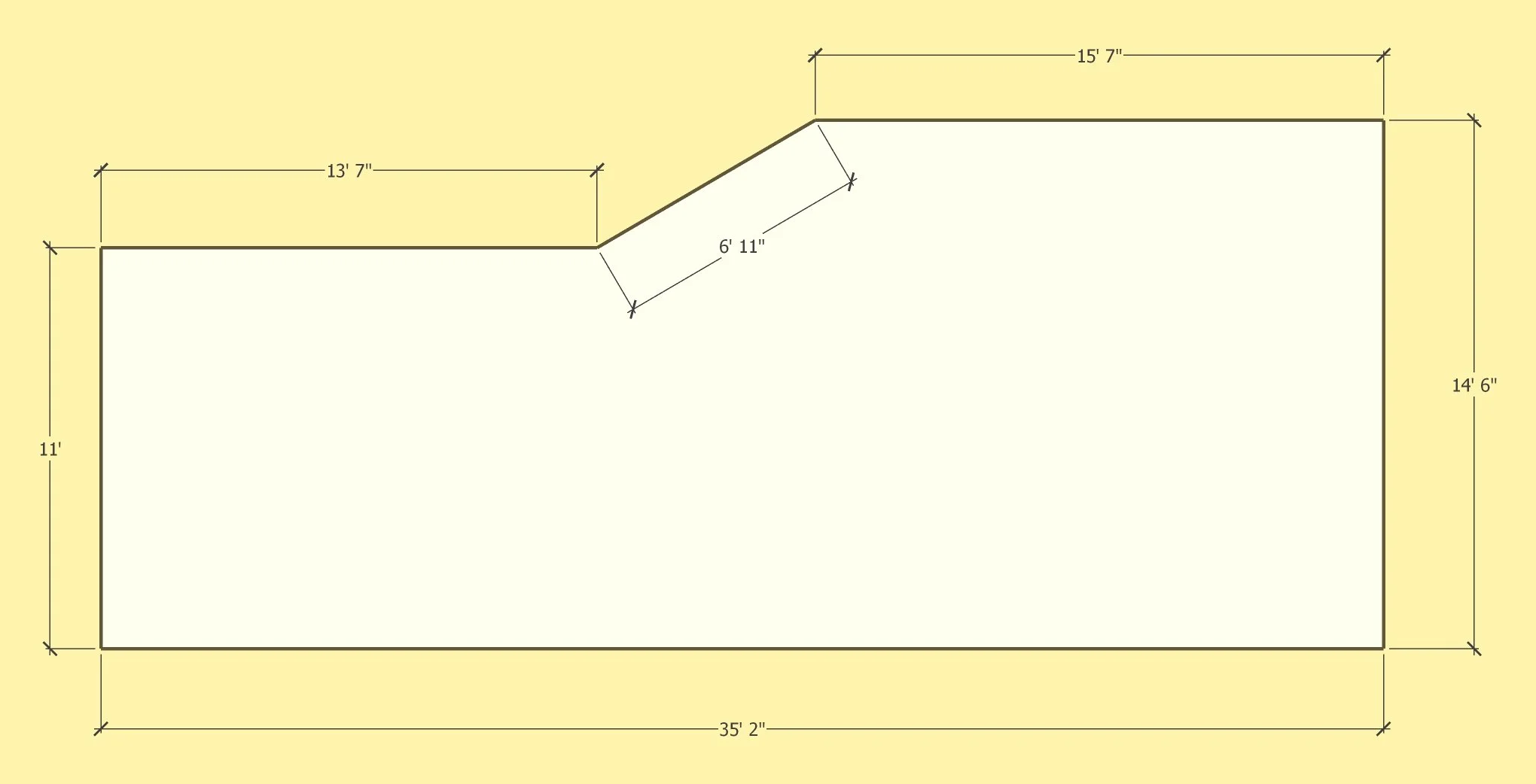
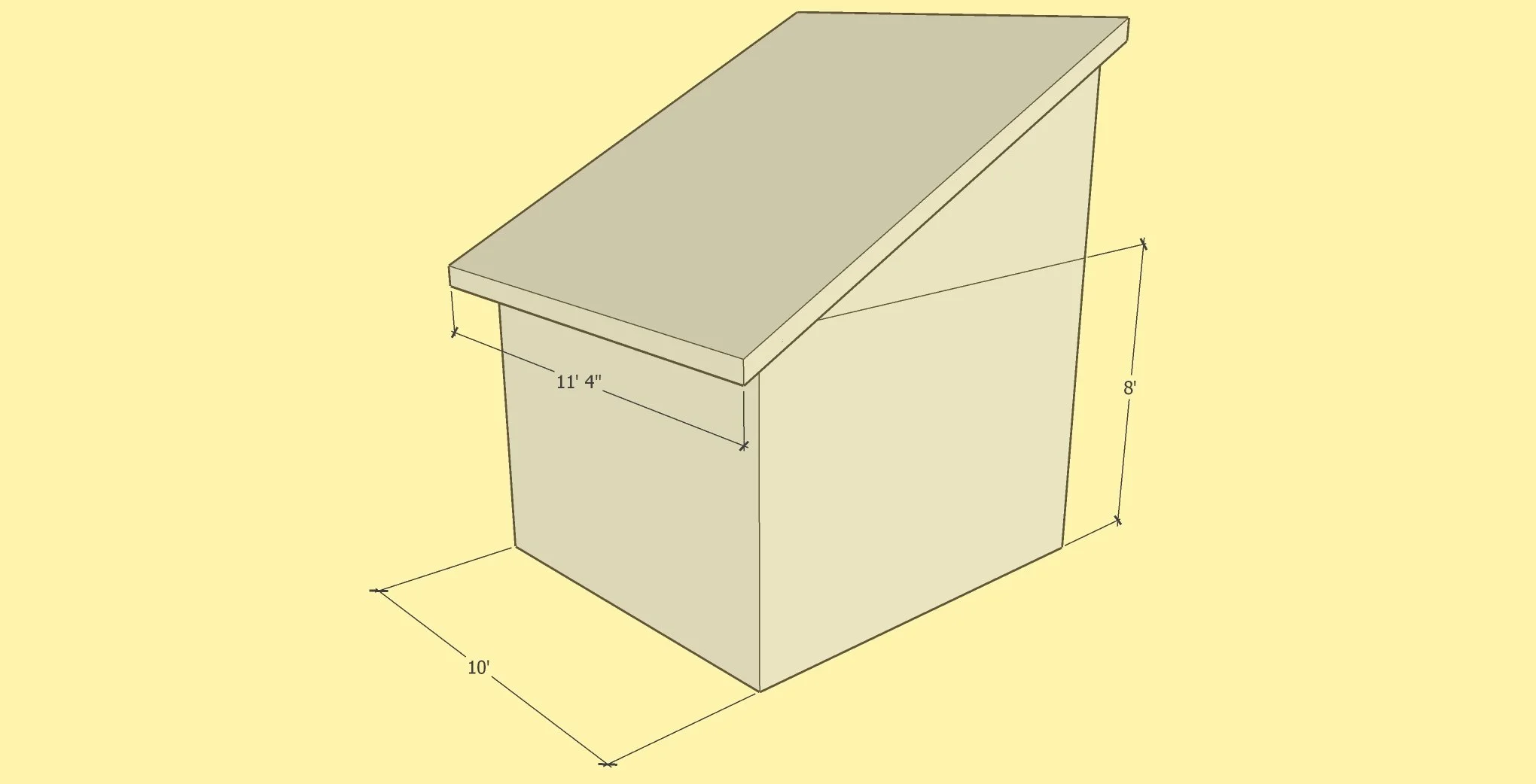
This project involved designing decks for an existing building. The customer had only a general idea of what she wanted, and it involved putting a roof over the front deck. The challenge was blending what appealed to the customer with what would satisfy building codes. Resolving the roof lines was where CAD made the job much easier than traditional drafting methods. All of the mathematical calculations are done with precision by the CAD software.
The most important aspect of the project was to produce drawings that would enable a builder to estimate the cost of doing the work. Our job was to provide everything a builder would need for the estimate, and nothing more. A general image of what was wanted, along with all of the critical dimensions is what is shown below.
It should be noted that it was the customer who was the actual designer … we simply executed her design in CAD.


Building decks is a common project for a homeowner. There are many designs and methods of deck construction. Below is a video of a 16’ X 16’ deck. This design uses only 16’ lengths of material, keeping the waste to an absolute minimum.
Balustrade construction layout.
Balustrade construction is difficult enough for professionals, but extremely daunting for non-professionals.. We can provide whatever is necessary for precision results.
This image is an example of a baluster layout.

Pictured below is the printout of a layout which can be supplied if needed.


This image is a baluster layout for a staircase.
Pictured below is the printout of a layout which can be supplied if needed.
