The images below demonstrate the efficiency of designing in CAD.
This is an overall view of a dining room proposal. Editing details in the room can be difficult when walls block access to details beyond a wall.
With one click, any wall can be hidden, enabling the technician unobstructed access to any of the objects in the room. This makes the design process very efficient, and making it cost effective for the customer.


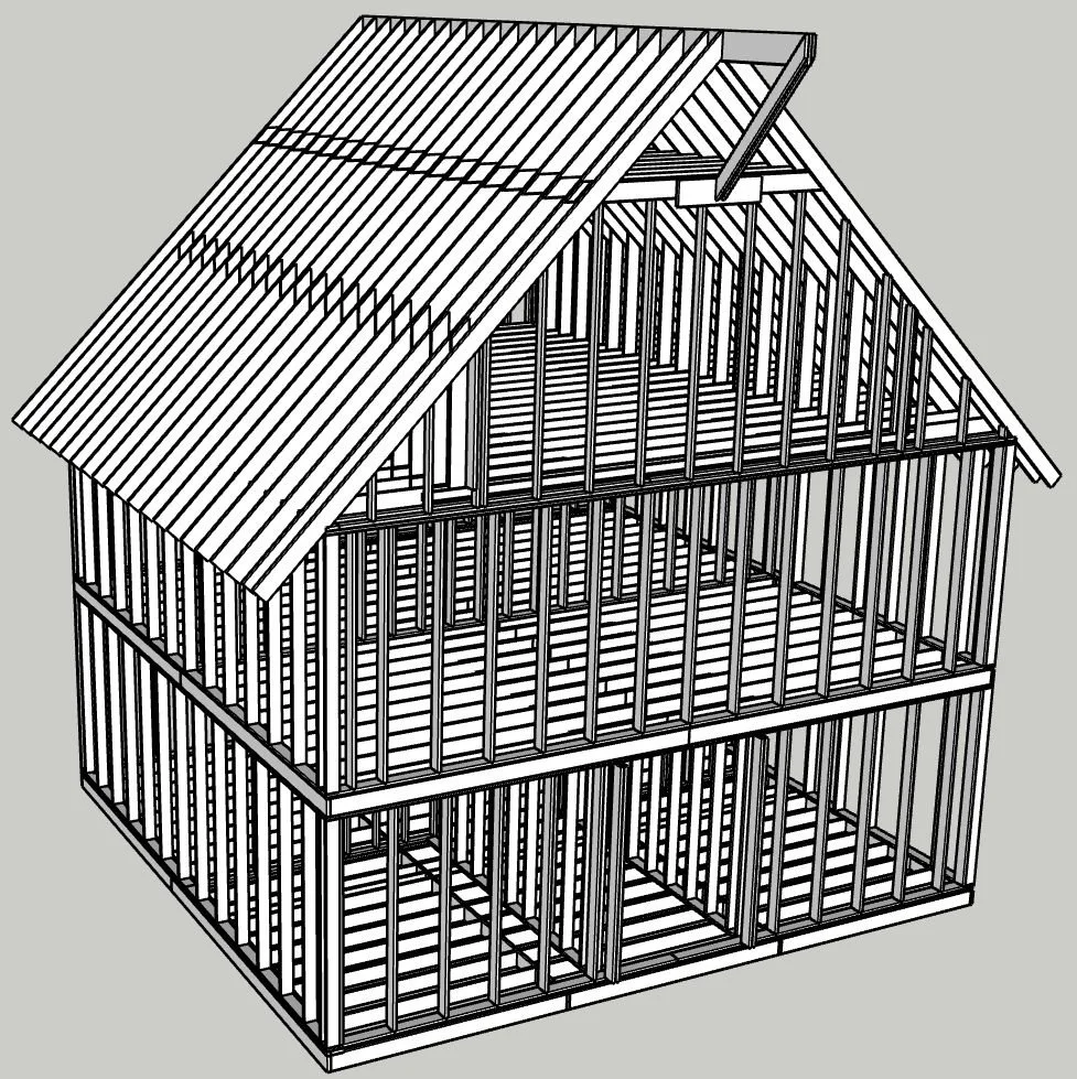
This model is the framing detail of an existing building which is going to be renovated. In order to design the extensive remodeling of the building, we had to start with the actual construction of the building. This required taking all the measurements, and then constructing the building in CAD. The original framing was unconventional, so the challenge is to design the changes to be made, insuring structural integrity, and maintaining compliance with existing building codes.
If a customer has a survey of a proposed, or existing building site, we can produce a model from the survey headings. Placing a new building on the site that is within building code setbacks is critical, and extremely important with smaller plots. Code officers will require accurate drawings before issuing a building permit.


Going from imagination to drawings a builder can work with.
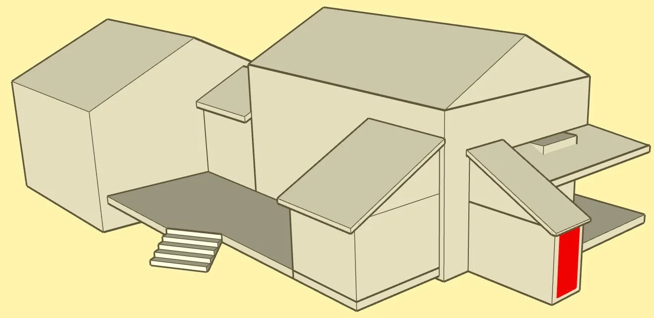
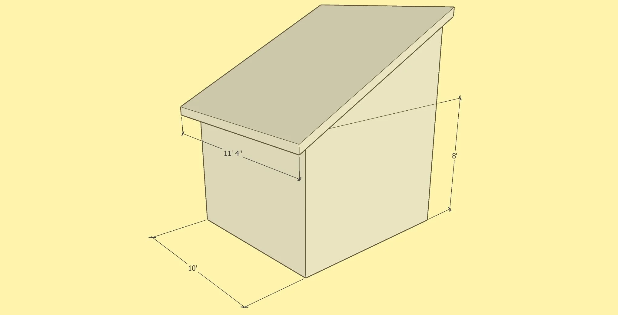
This project involved designing decks for an existing building. The customer had only a general idea of what she wanted, and it involved putting a roof over the front deck. The challenge was blending what appealed to the customer with what would satisfy building codes. Resolving the roof lines was where CAD made the job much easier than attempting to solve the roof geometry by calculation.
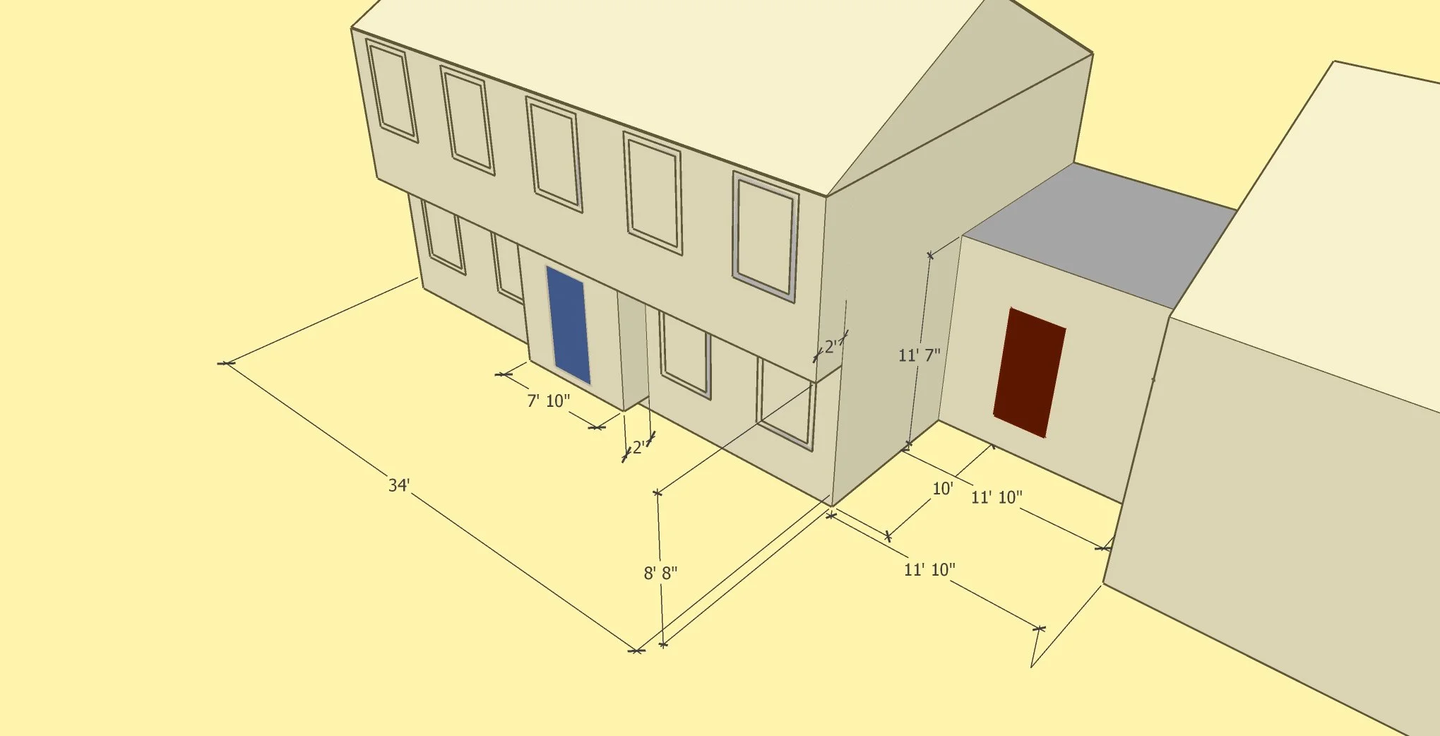
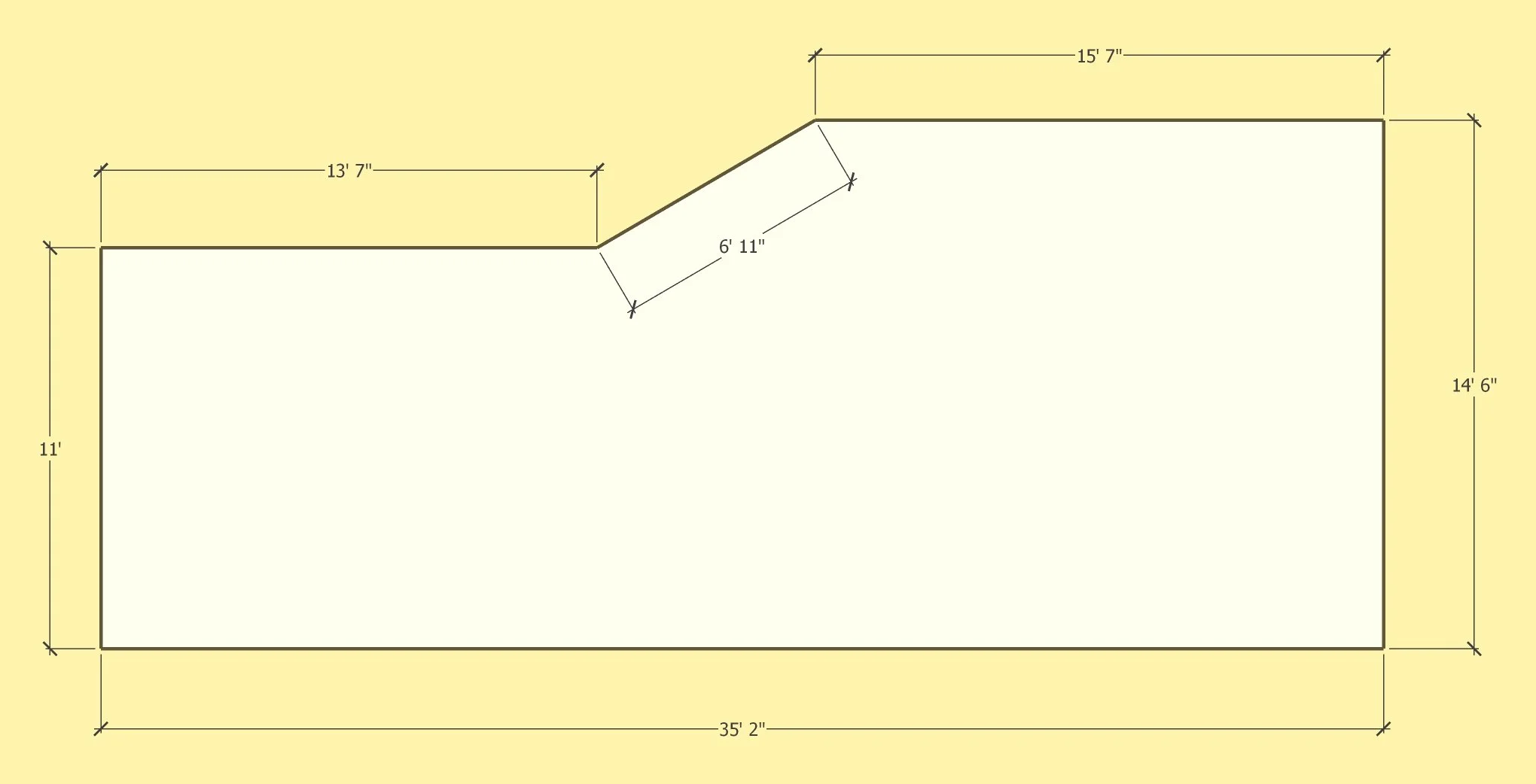
The most important aspect of the project was to produce drawings that would enable a builder to estimate the cost of doing the work. Our job was to provide everything a builder would need for the estimate, and nothing more. A general image of what was wanted, along with all of the critical dimensions is what is shown below.
It should be noted that it was the customer who was the actual designer … we simply executed her design in CAD.


This project involved making decisions about making a bathroom larger. The builder and the customer had settled on two scenarios.
Using CAD to visualize changes before beginning the actual construction.

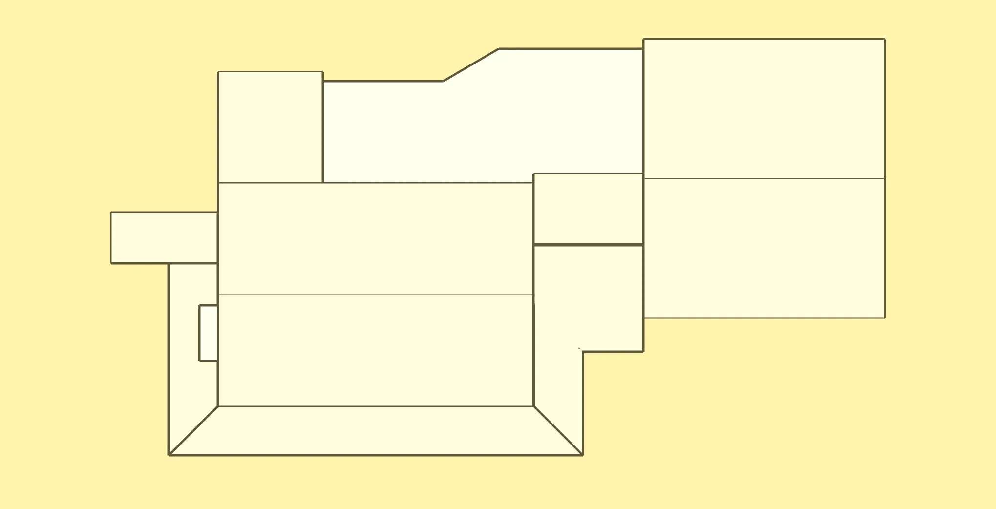
A fairly definite decision was made to bring the two walls (in yellow) closer together, keeping the window (in red) centered. What had to be determined was whether to move the walls in 7 or 10 inches. Both scenarios were modeled, so the customer could visualize what the results would actually look like.
7 INCH SCENARIO

Overhead View

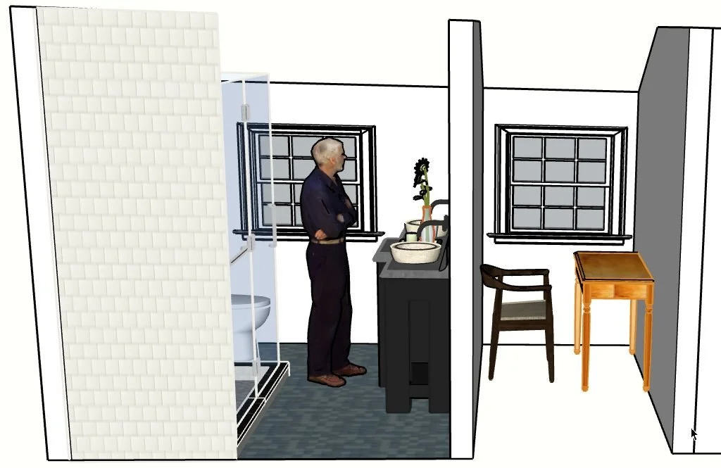
Side View
10 INCH SCENARIO
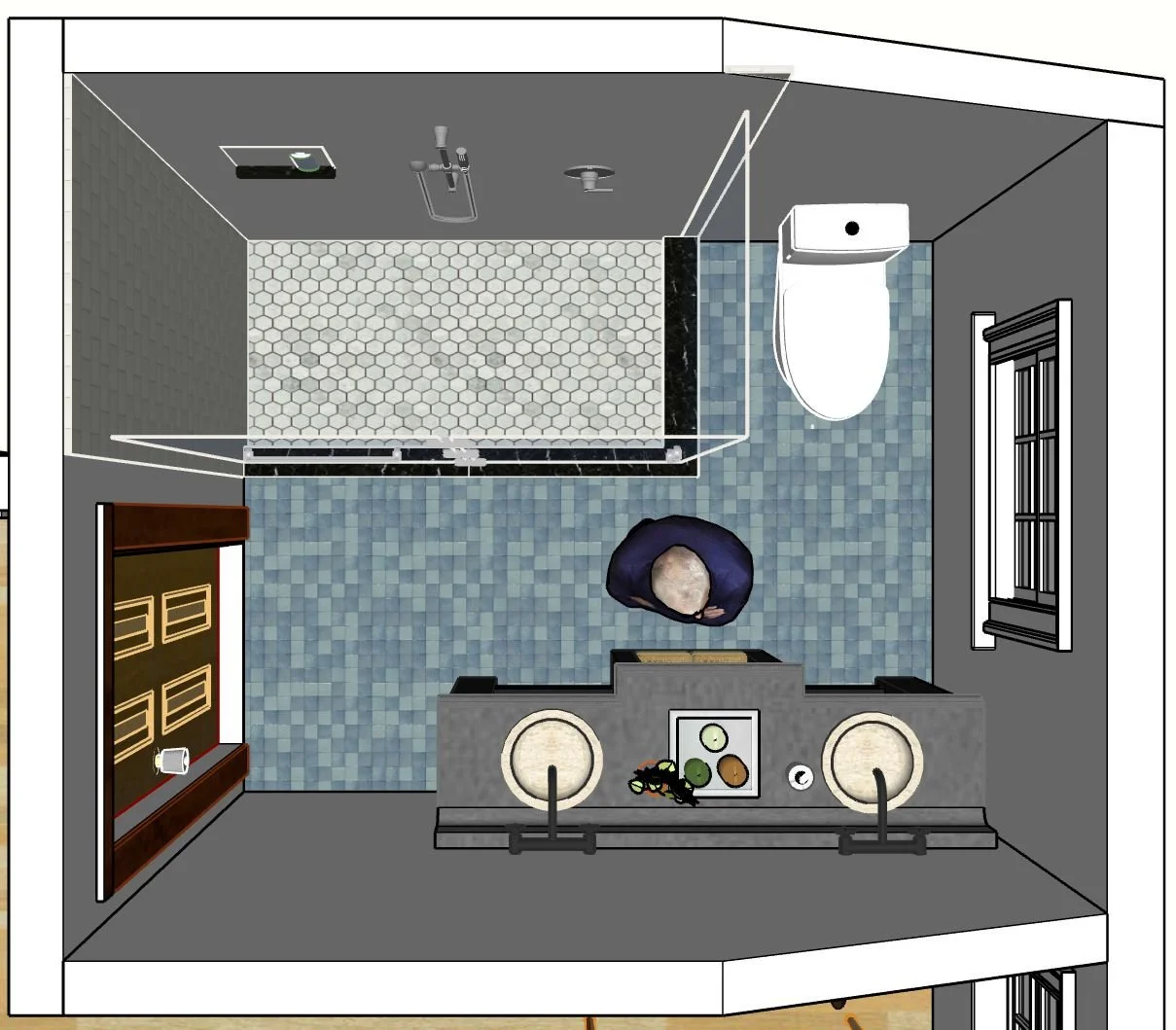
Overhead View
Side View
When the customer saw the two scenarios, she realized she did not want either option. It was finally decided to remove the existing wall, and have one large bathroom.
This project highlights the value in modeling possible changes before actually doing the work. Had either of the scenarios actually been completed, the customer would have spent a considerable amount of money, and would have been very unhappy with the results.
For contractors, the value of having the customer understand how something is actually going to turn out, CAN’T BE OVERSTATED.
Balustrade construction layout.
Balustrade construction is difficult enough for professionals, but extremely daunting for non-professionals.. We can provide whatever is necessary for precision results.
This image is an example of a baluster layout.

Pictured below is the printout of a layout which can be supplied if needed.


This image is a baluster layout for a staircase.
Pictured below is the printout of a layout which can be supplied if needed.
